Line Feature in SLAM
三维空间中的直线可以用两个过直线的三维空间点或者两个平面来定义。但是,相对于刚体变换在三维空间中的六个自由度:三个平移自由度和三个旋转自由度。它可以沿 x、y 和 z 轴中的任一轴平移,也可以绕其中任一轴或其他三个正交方向中的任一轴旋转。直线在三维空间中只有 4 个自由度,这是因为当它以自己为轴旋转或沿自己的方向平移时,它仍是同一条直线。下文中将介绍三维空间中直线的四种参数化方式:普吕克直线参数法 (Plücker Line Coordinates) 、正交表达法 (Orthonormal Representation) 、四元数与距离表示法 (quaternion and distance scalar) 、最近点法 (closest point) 。1 2 3 4 5 6 7
其中由于其简单性,由 6 个参数组成的普吕克线坐标可以方便直线参与几何运算(变换和投影)。而因为空间中的直线只有 4 个自由度,而 Plücker 参数化方法需要使用 6 个参数表示直线,这样就会导致过参数化,过参数化在优化的时候就需要采用带约束的优化,不太方便。于是引入了可以用 4 个参数化形式更新直线的其余三种方法来用于优化。这些参数化方法可以很方便的相互转换,所以可以在 SLAM 系统中同时使用这些参数化形式,在初始化和进行空间变换的时候使用 Plücker 坐标,在优化的时候使用其余三种表示。下面我们就来详细了解这些参数化方法和优化的雅克比求导。
1. 普吕克参数法
1.1 使用空间中的两点推演
假设在三维空间中点 $P_1,P_2 \in \mathbb R^3$ 是直线 $\cal L$ 上的任意两个点,它们的齐次坐标形式分别为 $\bar P_1 = [x_1, y_1, z_1, w_1]^T$ 和 $\bar P_2 = [x_2, y_2, z_2, w_2]^T$ 。其中 $w_1, w_2$ 是为了齐次坐标的更通用表达,表示三维空间点时有 $w_1=w_2=1$ 。由此,直线 $\cal L$ 可以用 6 个参数的普吕克坐标表示为: $$ \begin{gather*} \mathcal L = [L_1, L_2, L_3, L_4, L_5, L_6]^T \newline L_1 = y_1 z_2 - z_1 y_2 \qquad\quad L_4 = w_1 x_2 - w_2 x_1 \newline L_2 = z_1 x_2 - x_1 z_2 \qquad\quad L_5 = w_1 y_2 - w_2 y_1 \newline L_3 = x_1 y_2 - y_1 x_2 \qquad\quad L_6 = w_1 z_2 - w_2 z_1 \end{gather*} \tag{1}\label{1} $$ 当 $w_1=w_2=1$ 时,由直线和坐标原点构成的平面 $\pi$ 的法向量 $\bf n$ 和直线的方向向量 $\bf v$ 分别为: $$ \begin{alignat*}{2} \mathbf n &= P_1 \times P_2 & & = [L_1, L_2, L_3]^T \newline \mathbf v &= P_2 - P_1 & &= [L_4, L_5, L_6]^T \end{alignat*}\tag{2}\label{2} $$ 所以直线 $\cal L$ 的 Plücker 坐标表示为 $\mathcal L = (\mathbf n^T, \mathbf v^T)^T \in \mathbb R^6 \subset \mathbb P^5$ 是由 $\mathbf n \in \mathbb R^3$ 和 $\mathbf v \in \mathbb R^3$ 组成的 6 维向量。其中 $\bf v$ 是直线的方向向量,$\bf n$ 是由直线和坐标原点构成的平面 $\pi$ 的法向量,如 Fig. 1 所示。
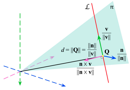
如果选择另外两个直线 $\cal L$ 上的点来构建 Plücker 坐标,则有: $$ \begin{gather*} P_1’ = \alpha P_1 + (1-\alpha)P_2 \qquad \quad P_2’ = \beta P_1 + (1-\beta) P_2 \newline \mathbf n’ = P_1’ \times P_2’ = (\alpha - \beta)\mathbf n \newline \mathbf v’ = P_2’ - P_1’ = (\alpha - \beta)\mathbf v \end{gather*} \tag{3}\label{3} $$ 由此可以知道同一直线的不同普吕克坐标参数相差一个尺度因子,即虽然普吕克坐标是 6 个参数,但只有 5 个自由度。另外 $\mathbf n^T \mathbf v = 0$ 构建的一个约束将直线在空间中的自由度降低到 4 个。需要注意的是 Plücker 坐标中的法向量和方向向量都不必是单位向量,且不可以独立分别对其作归一化处理。因为它们的模长比值 $\lVert \mathbf n \rVert / \lVert \mathbf v \rVert$ 具有实际性的物理意义。从另一个角度来说明,由式 $\eqref{2}$ 变形可得:$\mathbf n = P_1 \times \mathbf v$ 。假设 $P$ 也是直线 $\cal L$ 上的点 $P - P_1 = \lambda \mathbf v$ ,则有 $$ \begin{align*} P \times \mathbf v &= (P_1 + \lambda \mathbf v) \times \mathbf v \newline &= P_1 \times \mathbf v + \lambda \mathbf v \times \mathbf v \newline &= \mathbf n \end{align*} \tag{4}\label{4} $$ 由此可见,对于任意 $\lambda$ 值,式 $\eqref{4}$ 都成立。所以这里的 $\bf n$ 与任意点 $P$ 是无关的。另外见 Fig. 1 ,假设坐标原点和直线垂直相交于点 $Q$,有 $$ \lVert \mathbf n \rVert = \lVert Q \times \mathbf v \rVert = \lVert Q \rVert \lVert \mathbf v \rVert \sin(\pi / 2) \quad\to\quad \lVert Q \rVert = \cfrac{\lVert\mathbf n \rVert}{\lVert \mathbf v \rVert} \tag{5}\label{5} $$ 即原点到直线的距离 $d = \lVert Q \rVert = \frac{\lVert\mathbf n \rVert}{\lVert \mathbf v \rVert}$ 。
1.2 过原点或无穷远直线的普吕克坐标
如果 $\mathbf n = \bf 0$ 且 $\mathbf v \neq \bf 0$ ,则直线通过原点。根据式 $\eqref{4}$ ,因为直线过原点,那么把 $P$ 设为原点,则 $\mathbf n = \mathbf 0 \times \mathbf v = \mathbf 0$ ,跟它的实际意义相符。如 Fig. 2 - (a) 所示:
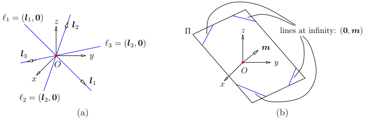
根据 Fig. 1 ,在平面 $\pi$ 内,将直线 $\cal L$ 沿着直线上任意一点 $P$ 的方向平移距离 $t$ ,此时,新直线的普勒克坐标变为 $[\mathbf v^T, (tP\times \mathbf v)^T]^T = [\mathbf v^T, t\mathbf n^T]^T = [\mathbf v^T / t, \mathbf n^T]$ ,当 $t \to \infty$ 时,则直线被移到至无穷远处,则有 $\mathbf n \neq \bf 0$ 且 $\mathbf v = \bf 0$ 。如 Fig. 2 - (b) 所示。由此可知,无穷远处的平行线位于通过原点的不同平面上,因此具有不同的 $\bf n$ 值。
Plücker 坐标不包括 $[\mathbf 0, \mathbf 0]$ 。 它们被认为是齐次坐标(在五维射影空间中),唯一地表示三维空间中的线。
1.3 使用空间中两个平面相交表示
根据上面的的推演并结合空间中点与线的对偶形式,给定 3D 空间中的两个平面 $I = (\bar I, i), J=(\bar J, j)$ ,这里的 $i,j$ 表示截距,同样,按照 Plücker 坐标的表示,有: $$ \mathcal L = \begin{bmatrix} \mathbf n \newline \mathbf v \end{bmatrix} = \begin{bmatrix} i \bar J - j \bar I \newline \bar I \times \bar J \end{bmatrix} \tag{6}\label{6} $$ 其中,易得两个平面相交的直线的方向向量为两个平面法向量的叉积。而上式中的 $\bf n$ ,可以假设点 $P$ 在直线上,所以点 $P$ 也一定在两个平面上,则有
$$ \begin{cases} \bar I P + i = 0 \newline \bar J P + j = 0 \end{cases} \quad\to\quad (i\bar J - j \bar I)P = 0 \tag{7} \label{7} $$
所以 $\mathbf n = i\bar J - j \bar I$ 垂直于直线上的任意一点,同时 $\bf n$ 也垂直于直线的方向向量 $\bf v$ ,因此 $\bf n$ 就是直线与原点构成平面的法向量。
1.4 空间直线的 Plücker 坐标变换
当给定从世界坐标系 $w$ 到相机坐标系 $c$ 的变换矩阵 $T_{cw} = \begin{bmatrix} R_{cw} & t_{cw} \newline 0 & 1 \end{bmatrix}$ ,可以通过下面的式子将世界坐标系下的 Plücker 线坐标转换到相机坐标系下 8 : $$ \begin{align*} \mathcal L^c = \begin{bmatrix} \mathbf n^c \newline \mathbf v^c \end{bmatrix} = \mathcal T_{cw} \mathcal L^w &= \begin{bmatrix} R_{cw} & \lfloor t_{cw} \rfloor_\times R_{cw} \newline 0 & R_{cw} \end{bmatrix} \begin{bmatrix} \mathbf n^w \newline \mathbf v^w \end{bmatrix} \newline &= \begin{bmatrix} R_{wc}^T & \lfloor -R_{wc}^Tt_{wc} \rfloor_\times R_{wc}^T \newline 0 & R_{wc}^T \end{bmatrix} \begin{bmatrix} \mathbf n^w \newline \mathbf v^w \end{bmatrix} = \begin{bmatrix} R_{wc}^T & -R_{wc}^T\lfloor t_{wc} \rfloor_\times \newline 0 & R_{wc}^T \end{bmatrix} \begin{bmatrix} \mathbf n^w \newline \mathbf v^w \end{bmatrix} \end{align*} \tag{8.a} \label{8.a} $$
式 $\eqref{8.a}$ 中矩阵第一行的推导如下,由式 $\eqref{2}$ 可得:
$$ \begin{align*} \mathbf n^c &= (T_{cw} \bar P_1^w) \times (T_{cw} \bar P_2^w) \newline &= (R_{cw} P_1^w + t_{cw}) \times (R_{cw} P_2^w + t_{cw}) \newline &= R_{cw} P_1^w \times R_{cw} P_2^w + R_{cw} P_1^w \times t_{cw} + t_{cw} \times R_{cw} P_2^w \newline &= R_{cw} (P_1^w \times P_2^w) + t_{cw} \times R_{cw} (P_2^w - P_1^w) \newline &= \begin{bmatrix} R_{cw} & \lfloor t_{cw} \rfloor_\times R_{cw} \end{bmatrix} \begin{bmatrix} P_1^w \times P_2^w \newline P_2^w - P_1^w \end{bmatrix} \newline &= \begin{bmatrix} R_{cw} & \lfloor t_{cw} \rfloor_\times R_{cw} \end{bmatrix} _{3\times6} \begin{bmatrix} \mathbf n^w \newline \mathbf v^w \end{bmatrix} _{6\times1} \end{align*} \tag{8.b} \label{8.b} $$
式 $\eqref{8.a}$ 中矩阵第二行易得。式 $\eqref{8.a}$ 中的 $\mathcal T_{cw}$ 表示为从世界坐标系 $w$ 到相机坐标系 $c$ 的 Plücker 线坐标转换矩阵。同理,可以定义逆矩阵,将直线 Plücker 坐标从坐标系 $c$ 变换到世界坐标系 $w$ 下: $$ \mathcal T_{cw}^{-1} = \begin{bmatrix} R_{cw}^T & \lfloor -R_{cw}^T t_{cw} \rfloor_\times R_{cw}^T \newline 0 & R_{cw}^T \end{bmatrix} = \begin{bmatrix} R_{cw}^T & -R_{cw}^T\lfloor t_{cw} \rfloor_\times \newline 0 & R_{cw}^T \end{bmatrix} \tag{8.c} \label{8.c} $$
1.5 空间直线在 Plücker 坐标中的初始化
梳理下空间直线在 Plücker 坐标中的初始化/三角化,下文主要参考文献 3 4 7 ,另外还有的的求解方式可以参考 1 7 。
1.5.1 最小二乘法
将滑动窗口中第 $i$ 幅图像中的一条直线的端点分别记为 $\mathbf x_{si}$ 和 $\mathbf x_{ei}$(见 Fig. 3),我们就得到了由直线 $\mathbf x_l$ 和第 $i$ 个摄像机中心形成的平面 $\pi_i$ 的法线方向:
$$
{}^{C_i} \mathbf n_{ei} = \frac{\lfloor \mathbf x_{si} \rfloor_\times \mathbf x_{ei}}{\lVert \lfloor \mathbf x_{si} \rfloor_\times \mathbf x_{ei} \rVert} \tag{9} \label{9}
$$
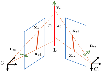
在滑动窗口中如果有多个匹配,则本质上就是在求解最小二乘问题了。由于直线 $\mathbf x_l$ 位于每个平面 $\pi_i$ 上,因此有以下约束条件:
$$ \underbrace{ \begin{bmatrix} \vdots \newline {}^{C_2}\mathbf n_{e2}^T {}^{C_1} _{C_2} R^T \newline \vdots \end{bmatrix} } _{N} {}^{C_1} \mathbf v _{e1} = \mathbf 0 \tag{10} \label{10} $$
因此,${}^{C_1} \mathbf v_{e1}$ 可以作为最小化该约束条件误差的单位向量,由 $N^TN$ 最小特征值对应的特征向量给出。注意这里我们把 $c_1$ 当做了参考系,因此在 $c_1$ 系下,当通过公式 $\eqref{10}$ 得到了线特征的方向之后,我们就得到了线特征在 $c_1$ 系下的两个参数 ${}^{C_1} \mathbf n_{e1}, {}^{C_1} \mathbf v_{e1}$,但是注意这里 ${}^{C_1} \mathbf n_{e1}$ 是单位向量,与普吕克表示法中的 $\bf n$ 差一个距离 $d$ ,下面是 $d$ 的求解。
将 $c_i$ 框架中表示的直线转换为 $c_1$ 框架中表示的直线,由 $\eqref{8.a}$ 可知其转换过程如下:
$$ \begin{bmatrix} {}^{C_1} d_l {}^{C_1}\mathbf n_{e1} \newline {}^{C_1}\mathbf v_{e1} \end{bmatrix} = \begin{bmatrix} {}^{C_1} _ {C_i}R & \lfloor {}^{C_1}\mathbf t_{C_i} \rfloor_\times {}^{C_1} _ {C_i}R \newline \mathbf 0_3 & {}^{C_1} _ {C_i}R \end{bmatrix} \begin{bmatrix} {}^{C_i} d_l {}^{C_i}\mathbf n_{ei} \newline {}^{C_i}\mathbf v _{ei} \end{bmatrix} \tag{11.a} \label{11.a} $$
取出矩阵中第一行得到
$$ {}^{C_1} d_l {}^{C_1}\mathbf n_{e1} = {}^{C_i} d_l {}^{C_1} _ {C_i}R {}^{C_i}\mathbf n_{ei} + \lfloor {}^{C_1}\mathbf t_{C_i} \rfloor_\times {}^{C_1} _ {C_i}R {}^{C_i}\mathbf v_{ei} \tag{11.b} \label{11.b} $$
由于我们仅想求解 ${}^{C_1}d_l$ ,所以我们通过两边同时乘以与 ${}^{C_1} _ {C_i}R {}^{C_i}\mathbf n_{ei}$ 垂直的单位向量 $\mathbf b_i = \lfloor {}^{C_1} \mathbf v_{e1} \rfloor_\times {}^{C_1} _ {C_i}R {}^{C_i}\mathbf n_{ei}$ 来消除带有 ${}^{C_i}d_l$ 的项,得
$$ {}^{C_1}d_l \mathbf b_i^T {}^{C_1} \mathbf n_{e1} = \mathbf b_i^T \lfloor {}^{C_1}\mathbf t_{C_i} \rfloor_\times {}^{C_1} _ {C_i}R {}^{C_i}\mathbf v_{ei} \tag{11.c} \label{11.c} $$
于是我们看到,上面的公式 $\eqref{11.c}$ 中所有的向量和旋转我们都是在之前计算过得,仅有一个未知量 ${}^{C_1}d_l$ ,依旧结合多个观测之后,可以得到:
$$ {}^{C_1}d_l \begin{bmatrix} \vdots \newline \mathbf b_i^T {}^{C_1} \mathbf n_{e1} \newline \vdots \end{bmatrix} = \begin{bmatrix} \vdots \newline \mathbf b_i^T \lfloor {}^{C_1}\mathbf t_{C_i} \rfloor_\times {}^{C_1} _ {C_i}R {}^{C_i}\mathbf v_{ei} \newline \vdots \end{bmatrix} \tag{11.d} \label{11.d} $$
这依旧求解一个最小二乘问题就可以了。经过公式 $\eqref{10}$ 和公式 $\eqref{11.d}$ 之后,线特征的三个要素 $\mathbf n, \mathbf v, d$ 就都知道了,于是就可以得到直线在 $c_1$ 坐标系下的普吕克坐标了。
1.5.2 普吕克矩阵法
1.5.2.a Plücker 矩阵 $\mathbf L^*$
当我们从不同的两帧相机观测到一个新的线路标的时候,Plücker 坐标初始化方式也很简单。如 Fig. 4 中所示,直线 $\cal L$ 在两帧图形 $c_1$ 和 $c_2$ 中表示为两个线段 $z_\mathcal L^{c_1}$ 和 $z_\mathcal L^{c_2}$ 。线段 $z_\mathcal L^{c_1}$ 在归一化平面可以被两个端点表示,$s^{c_1} = \begin{bmatrix} u_s & v_s & 1 \end{bmatrix}^T$ 和 $e^{c_1} = \begin{bmatrix} u_e & v_e & 1 \end{bmatrix}^T$ 。再加上相机坐标原点 $C = [x_0, y_0, z_0 ]^T$ ,这三个点可以确定一个平面:$\pi = \begin{bmatrix} \pi_x & \pi_y & \pi_z & \pi_w \end{bmatrix}$ 。有
$$
\pi_x(x - x_0) + \pi_y (y-y_0) + \pi_z(z - z_0) = 0 \tag{12.a} \label{12.a}
$$
其中,
$$
\begin{bmatrix} \pi_x \newline \pi_y \newline \pi_z \end{bmatrix} = \lfloor s^{c_1} \rfloor_\times e^{c_1} \ , \qquad \pi_w = \pi_x x_0 + \pi_y y_0 + \pi_z z_0 \tag{12.b} \label{12.b}
$$
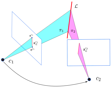
然后对同一个空间直线在两帧相机平面的投影和相机光心可以确定两个平面 $\pi_1$ 和 $\pi_2$ ,通过两个平面可以确定唯一的空间直线。有了这两个平面我们可以得到对偶 Plücker 矩阵 $\mathbf L^*$ ,
$$ \mathbf L^* = \begin{bmatrix} \lfloor \mathbf v \rfloor_\times & \mathbf n \newline -\mathbf n^T & 0 \end{bmatrix} = \pi_1 \pi_2^T - \pi_2 \pi_1^T \in \mathbb R^{4\times4} \tag{13} \label{13} $$
然后从对偶矩阵中可以提取出 Plücker 坐标 $\mathcal L = (\mathbf n^T, \mathbf v^T)^T$ 。
1.5.2.b 普吕克矩阵法初始化
普吕克矩阵法也很简单,在多视图几何中有专门的章节进行介绍,其有点表示和面表示,两者相互对偶。本文中主要讨论面表示法,因为面的法向量是比较好获取的。利用式 $\eqref{13}$ 结合 Fig. 3 中的变量有, $$ \mathbf L^* = \pi_1 \pi_i^T - \pi_i \pi_1^T = \begin{bmatrix} \lfloor {}^{C_1} \mathbf v_{e1}^{(i)} \rfloor_\times & {}^{C_1} d_l^{(i)} {}^{C_1} \mathbf n_{e1}^{(i)} \newline -{}^{C_1} d_l^{(i)} ({}^{C_1} \mathbf n_{e1}^{(i)})^T & 0 \end{bmatrix} \tag{14} \label{14} $$ 其中 $\pi_1 = \begin{bmatrix} {}^{C_1}\mathbf n_{e1}^T & 0 \end{bmatrix}^T$ 和 $\pi_i = \begin{bmatrix} {}^{C_1}\mathbf n_{ei}^T & {}^{C_1}\mathbf n_{ei}^T {}^{C_1} \mathbf p_{C_i} \end{bmatrix}^T$ 。${}^{C_1} d_l^{(i)}, {}^{C_1}\mathbf n_{e1}^{(i)}$ 和 ${}^{C_1} \mathbf v_{e1}^{(i)}$ 表示根据 $\pi_1$ 和 $\pi_i$ 计算出的线性几何元素。对多帧观测得到的在 $c_1$ 坐标系的线特征取了一个平均,如下:
$$ \begin{align*} {}^{C_1}\mathbf n_{e1} &= \sum_{i=2}^m {}^{C_1}\mathbf n_{e1}^{(i)} / \bigg\lVert \sum_{i=2}^m {}^{C_1}\mathbf n_{e1}^{(i)} \bigg\rVert \tag{15.a} \label{15.a} \newline {}^{C_1}\mathbf v_{e1} &= \sum_{i=2}^m {}^{C_1}\mathbf v_{e1}^{(i)} / \bigg\lVert \sum_{i=2}^m {}^{C_1}\mathbf v_{e1}^{(i)} \bigg\rVert \tag{15.b} \label{15.b} \newline {}^{C_1} d_l &= \frac{\sum^m_{i=2} {}^{C_1}d_l^{(i)}}{m-1} \tag{15.c} \label{15.c} \end{align*} $$
1.5.3 线特征初始化的退化运动分析
在使用单目摄像机时,进行线特征三角测量的能力在很大程度上取决于传感器的运动。特别是,我们识别出了导致线特征参数无法观测的退化运动,从而导致三角测量失败。
- 如果单目摄像机沿线 $\cal L$ 的方向 $\bf v$ 或以 $\mathbf v \times \mathbf n$ 的方向朝 $\cal L$ 移动,摄像机将保持在同一平面 $\pi$ 上。此时通过线观测得到的两个平面法向量平行,无法得到线特征的方向向量
- 如果单目摄像机进行纯粹的旋转(无平移),那么摄像机也会停留在平面 $\pi$ 上,从而导致与前一种情况相同的退化现象
- 直线三角测量的有效运动是垂直于平面 $\pi$ 的运动

需要注意的是,对于单目摄像机来说,上述 3 种退化运动的任何组合都会导致三角测量失败。对于立体摄像机来说,如果在运动过程中双目看到的线与相机中心构成的平面相互平行,仍然会有退化运动。在这种情况下,即使是立体视觉也无法保证正确的线三角测量。
1.6 直线的投影方程和误差函数
1.6.1 投影方程
要想知道线特征的观测模型,我们需要知道线特征从归一化平面到像素平面的投影内参矩阵 $\cal K$ 。如 Fig. 5 ,点 $C$ 和 $D$ 是直线 $\mathcal L = (\mathbf n^T, \mathbf v^T)^T$ 上的两点,点 $\bf c$ 和 $\bf d$ 是它们在像素平面上的投影。$\mathbf c=KC, \mathbf d=KD$ ,$K$ 是相机的内参矩阵。
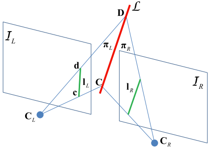
对于归一化平面和相机平面,两者其实都是 2 维的射影平面,所以在归一化平面和齐次像平面上的直线的表示为 $\mathbf n = \lfloor C \rfloor_\times D, \mathbf l = [l_1, l_2, l_3]^T = \lfloor \mathbf c \rfloor_\times \mathbf d$ 。则有 $$ \mathbf l = \mathcal K \mathbf n = \begin{bmatrix} f_y & 0 & 0 \newline 0 & f_x & 0 \newline -f_y c_x & -f_x c_y & f_x f_y \end{bmatrix} \mathbf n \tag{16} \label{16} $$ 可以从 $\lfloor \mathbf c \rfloor_\times \mathbf d = \lfloor KC \rfloor_\times KD$ 进行展开推导证明。因为两个归一化平面的点的叉乘就是在相机坐标系下的 Plücker 表示中的法向量,因此可以看到在归一化坐标系到图像坐标系的转换中,仅仅涉及到了直线表示中的法向量部分。由此表明,直线的线投影只和法向量有关和方向向量无关。
1.6.2 误差函数
我们将线的投影误差定义为图像中观测线段的端点到从空间重投影回像素平面的预测直线的距离,如 Fig. 6 所示。
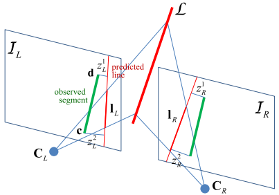
$$ \mathbf r_\mathbf l = \begin{bmatrix} r_1 \newline r_2 \end{bmatrix} = \begin{bmatrix} \cfrac{\mathbf c^T \mathbf l}{\sqrt{l_1^2 + l_2^2}} \newline \cfrac{\mathbf d^T \mathbf l}{\sqrt{l_1^2 + l_2^2}} \end{bmatrix} \tag{17} \label{17} $$
2. 线特征的其它参数法
前文说到,由 6 个参数组成的普吕克线坐标可以方便直线参与几何运算,然而过参数化在优化求解的时候就需要采用带约束的优化,不太方便。下面我们在接下其余的三种参数化方式,它们可以方便的在优化过程中使用。正交表示法、四元数与距离表示法 、最近点法主要的贡献点在于可以使得整个表示的未知数与自由度是对应的,也就是可以用最小表示进行线特征的表示,这样的好处对于优化问题是不言而喻的,就和李群和李代数的关系一样。下面就简单的介绍一下这些表示方法。4 7 9
2.1 正交表示法
正交表示法的主要的思路是把普吕克坐标系看作是 $3\times2$ 的矩阵进行 QR 分解,得到的 Q 矩阵就是旋转矩阵,而 R 矩阵的自由度为 1,将其化简为 $SO(2)$ 进行优化。即四个参数的正交表示 $(U, W) \in SO(3) \times SO(2)$ 。见 Fig. 7 。
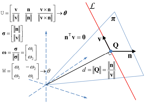
设直线的 Plücker 坐标 $\mathcal L = (\mathbf n^T, \mathbf v^T)^T$ ,将其写成矩阵形式 $[\mathbf n \quad \mathbf v]_{3\times2}$ 并降之进行 QR 分解, $$ \begin{bmatrix} \bf n & \bf v \end{bmatrix} = \begin{bmatrix} \cfrac{\bf n}{\lVert \mathbf n \rVert} & \cfrac{\bf v}{\lVert \mathbf v \rVert} & \cfrac{\bf n \times v}{\lVert \bf n \times v \rVert} \end{bmatrix} \begin{bmatrix} \lVert \mathbf n \rVert & 0 \newline 0 & \lVert \mathbf v \rVert \newline 0 & 0 \end{bmatrix} \tag{18} \label{18} $$ 分解得到的第一项是正交矩阵 $U$ ,是一个旋转矩阵。所表示的是相机坐标系到直线坐标系的旋转。其中直线坐标系的定义如下:用直线的方向向量以及直线和光心组成平面的法向量作为坐标的两个轴,再用他们叉乘得到的向量作为第三个轴,所以, $$ U = R(\boldsymbol\psi) = \begin{bmatrix} \cfrac{\bf n}{\lVert \mathbf n \rVert} & \cfrac{\bf v}{\lVert \mathbf v \rVert} & \cfrac{\bf n \times v}{\lVert \bf n \times v \rVert} \end{bmatrix} \tag{19} \label{19} $$ 其中 $\boldsymbol\psi = [\psi_1, \psi_2, \psi_3]^T$ 代表的是相机坐标系到直线坐标系在 $x, y$ 和 $z$ 轴的旋转角。由于将 $(\lVert \mathbf n \rVert,\lVert \mathbf v \rVert)$ 结合之后只有一个自由度,所以我们可以用三角函数矩阵参数化: $$ W = \begin{bmatrix} w_1 & -w_2 \newline w_2 & w_1 \end{bmatrix} = \begin{bmatrix} \cos(\phi) & -\sin(\phi) \newline \sin(\phi) & \cos(\phi) \end{bmatrix} = \frac{1}{\sqrt{\lVert\mathbf n \rVert^2 + \lVert\mathbf v \rVert^2}} \begin{bmatrix} \lVert \mathbf n \rVert & -\lVert \mathbf v \rVert \newline \lVert \mathbf v \rVert & \lVert \mathbf n \rVert \end{bmatrix} \tag{20} \label{20} $$ 上式中的 $\phi$ 是选择角。由于坐标原点(相机光心)到3D直线的距离是 $d = \frac{\lVert\mathbf n \rVert}{\lVert \mathbf v \rVert}$ ,所以 $W$ 包含了距离信息 $d$ 的。根据 $U$ 和 $W$ 的定义可以看出,4 个自由度包括旋转的 3 个自由度和距离的一个自由度。在优化的时候,使用 $\mathcal O = [\boldsymbol \psi, \phi]^T$ 作为空间直线更新的最小表示。
正交表示到 Plücker 坐标之间的变换可以通过下面的方式计算出来: $$ \mathcal L’ = [w_1 \mathbf u_1^T, w_2 \mathbf u_2^T]^T = \frac{1}{\sqrt{\lVert\mathbf n \rVert^2 + \lVert\mathbf v \rVert^2}} \mathcal L \tag{21} \label{21} $$ 其中 $\mathbf u_i$ 代表的是 $U$ 矩阵的第 $i$ 列,$w_1 = \cos(\phi)$ 和 $w_2 = \sin(\phi)$ 。虽然 $\cal L$ 和 $\cal L’$ 有一个尺度的差,但是它们表示的是同一条空间直线。
2.2 四元数与距离表示法
上面可以看到,其实线特征的自由度到最后就包括表征姿态的旋转矩阵 $SO(3)$ 和线到原点的距离 $d$,那么直接对这两个自由度进行优化而不像正交表示法一样再转换。由此这种方法把 $SO(3)$ 表示成四元数 $\bf q$ ,实际的自由度为 3,距离表示为 $d$ ,自由度为 1。所以四元数与距离的表示法如下,这里 $\boxplus$ 没有什么特别的意义,就是表示表达式需要加上距离: $$ \mathcal L \sim \underbrace{\begin{bmatrix} \cfrac{\bf n}{\lVert \mathbf n \rVert} & \cfrac{\bf v}{\lVert \mathbf v \rVert} & \cfrac{\bf n \times v}{\lVert \bf n \times v \rVert} \end{bmatrix}} _{U=R(\mathbf q)} \boxplus d \tag{22} \label{22} $$ 普吕克的转换关系如下: $$ \begin{gather} \mathcal L = \begin{bmatrix} \bf n \newline \bf v \end{bmatrix} = \begin{bmatrix} d \mathbf u_1 \newline \mathbf u_2 \end{bmatrix} \newline \mathbf u_1= R(\mathbf q) \begin{bmatrix} 1 \newline 0 \newline 0 \end{bmatrix} = R(\mathbf q) \mathbf e_1 \qquad \mathbf u_2= R(\mathbf q) \begin{bmatrix} 0 \newline 1 \newline 0 \end{bmatrix} = R(\mathbf q) \mathbf e_2 \end{gather} \tag{23} \label{23} $$
2.3 最近点法
该方法是作者4在上一个方法的基础上进行的改进,主要的想法是:因为四元数本身就是 4 个数,然后距离是 1 个数,所以作者就干脆把两者相乘,记作 $\mathbf p=d \mathbf q$,作者把这个 4D 的向量认为是一个点,这个点是距离空间中线的最近点,一个很大的好处就是这个更新的过程变作了加法,而不再是乘法了。 $$ \mathbf p = d\mathbf q = d\begin{bmatrix} q_w & \mathbf q_v^T \end{bmatrix}^T = \hat{\bf p} + \tilde{\bf p} \tag{24.a} \label{24.a} $$ 最近点法转换为上面的四元数与距离表达法其实很简单: $$ \begin{cases} \mathbf q = \cfrac{\mathbf p}{\lVert \mathbf p \rVert} \newline d = \lVert \mathbf p \rVert \end{cases} \tag{24.b} \label{24.b} $$ 于是与普吕克坐标表示的转换就可以参考上面的方法了。
2.4 总结
上述三种线特征表示方式可以方便的用于迭代优化中,下表总结出这三种线特征的表示形式与误差状态。

3. 线特征雅可比推导
根据 1.6.2 中的线特征测量误差定义,跟对 3D 点的优化问题一样,就是从误差不停的递推到位姿以及直线表示上,用到求导的链式法则: $$ \cfrac{\partial \bf r_l}{\partial X} = \cfrac{\partial \bf r_l}{\partial \bf l} \cfrac{\partial \bf l}{\partial \mathcal L^c} \begin{cases} \cfrac{\partial \mathcal L^c}{\partial \boldsymbol \theta} & X = \boldsymbol\theta \newline \cfrac{\partial \mathcal L^c}{\partial \mathbf t} & X = \mathbf t \newline \cfrac{\partial \mathcal L^c}{\partial \mathcal L^w} \cfrac{\partial \mathcal L^w}{\partial([\boldsymbol \psi, \phi]^T \ {\rm or} \ [\boldsymbol \psi, d]^T \ {\rm or} \ \mathbf p)} & X=\mathcal L^w \end{cases} \tag{25} \label{25} $$
3.1 $\frac{\partial \bf r_l}{\partial \bf l}$ 项
根据 $\mathbf c=[u_c, v_c , 1]^T, \mathbf d = [u_d, v_d, 1]^T, \mathbf l = [l_1, l_2, l_3]^T$ 与 $\eqref{17}$ 有 $$ \mathbf r_\mathbf l = \begin{bmatrix} r_1 \newline r_2 \end{bmatrix} = \begin{bmatrix} \cfrac{\mathbf c^T \mathbf l}{\sqrt{l_1^2 + l_2^2}} \newline \cfrac{\mathbf d^T \mathbf l}{\sqrt{l_1^2 + l_2^2}} \end{bmatrix} = \begin{bmatrix} \cfrac{u_c l_1 + v_c l_2 + l_3}{\sqrt{l_1^2 + l_2^2}} \newline \cfrac{u_d l_1 + v_d l_2 + l_3}{\sqrt{l_1^2 + l_2^2}} \end{bmatrix} \tag{26} \label{26} $$ 所以, $$ \begin{align} \frac{\partial \bf r_l}{\partial \bf l} &= \begin{bmatrix} \cfrac{\partial r_1}{\partial l_1} & \cfrac{\partial r_1}{\partial l_2} & \cfrac{\partial r_1}{\partial l_3} \newline \cfrac{\partial r_2}{\partial l_1} & \cfrac{\partial r_2}{\partial l_2} & \cfrac{\partial r_2}{\partial l_3} \end{bmatrix} \newline &= \begin{bmatrix} \cfrac{-l_1 \mathbf c^T \mathbf l}{(l_1^2 + l_2^2)^{\frac32}} + \cfrac{u_c}{(l_1^2 + l_2^2)^{\frac12}} & \cfrac{-l_2 \mathbf c^T \mathbf l}{(l_1^2 + l_2^2)^{\frac32}} + \cfrac{v_c}{(l_1^2 + l_2^2)^{\frac12}} & \cfrac{1}{(l_1^2 + l_2^2)^{\frac12}} \newline \cfrac{-l_1 \mathbf d^T \mathbf l}{(l_1^2 + l_2^2)^{\frac32}} + \cfrac{u_d}{(l_1^2 + l_2^2)^{\frac12}} & \cfrac{-l_2 \mathbf d^T \mathbf l}{(l_1^2 + l_2^2)^{\frac32}} + \cfrac{v_d}{(l_1^2 + l_2^2)^{\frac12}} & \cfrac{1}{(l_1^2 + l_2^2)^{\frac12}} \end{bmatrix}_{2\times3} \end{align} \tag{27} \label{27} $$
3.2 $\frac{\partial \bf l}{\partial \mathcal L^c}$ 项
由公式 $\eqref{16}$ 可知 $\mathbf l = \mathcal K \mathbf n_c$ ,有 $$ \frac{\partial \bf l}{\partial \mathcal L^c} = \begin{bmatrix} \cfrac{\partial \bf l}{\partial \mathbf n_c} & \cfrac{\partial \bf l}{\partial \mathbf v_c} \end{bmatrix} = \begin{bmatrix} \mathcal K & \mathbf 0 \end{bmatrix}_{3\times6} \tag{28} \label{28} $$
3.3 $\frac{\partial \mathcal L^c}{\partial \boldsymbol \theta}$ 项
根据式 $\eqref{8.a}$ 可知,
$$ \begin{align*} \frac{\partial \mathcal L^c}{\partial \boldsymbol \theta} = \begin{bmatrix} \cfrac{\partial \mathbf n_c}{\partial \boldsymbol\theta} \newline \cfrac{\partial \mathbf v_c}{\partial \boldsymbol\theta} \end{bmatrix} &= \begin{bmatrix} \cfrac{\partial (R_{wc}^T(\mathbf n_w - \lfloor\mathbf t_{wc} \rfloor_\times \mathbf v_w))}{\partial \boldsymbol\theta} \newline \cfrac{\partial R_{wc}^T \mathbf v_w}{\partial \boldsymbol\theta} \end{bmatrix} \newline &= \begin{bmatrix} \lfloor R_{wc}^T(\mathbf n_w - \lfloor\mathbf t_{wc} \rfloor_\times \mathbf v_w) \rfloor_\times \newline \lfloor R_{wc}^T \mathbf v_w \rfloor_\times \end{bmatrix}_{6\times3} \end{align*} \tag{29} \label{29} $$
上述的推导使用了李群的右扰动模型,即 $(R_{wc}{\rm Exp}(\boldsymbol\theta))^T = {\rm Exp}(-\boldsymbol\theta)R_{wc}^T$ 。
3.4 $\frac{\partial \mathcal L^c}{\partial \mathbf t}$ 项
根据式 $\eqref{8.a}$ 可知, $$ \frac{\partial \mathcal L^c}{\partial \mathbf t} = \begin{bmatrix} \cfrac{\partial \mathbf n_c}{\partial \mathbf t} \newline \cfrac{\partial \mathbf v_c}{\partial \mathbf t} \end{bmatrix} = \begin{bmatrix} \cfrac{\partial (R_{wc}^T(\mathbf n_w - \lfloor\mathbf t_{wc} \rfloor_\times \mathbf v_w))}{\partial \mathbf t} \newline \cfrac{\partial R_{wc}^T \mathbf v_w}{\partial \mathbf t} \end{bmatrix} = \begin{bmatrix} R_{wc}^T \lfloor \mathbf v_w \rfloor_\times \newline \mathbf 0 \end{bmatrix}_{6\times3} \tag{30} \label{30} $$
3.5 $\frac{\partial \mathcal L^c}{\partial \mathcal L^w}$ 项
根据式 $\eqref{8.a}$ 可知, $$ \frac{\partial \mathcal L^c}{\partial \mathcal L^w} = \begin{bmatrix} R_{wc}^T & -R_{wc}^T\lfloor t_{wc} \rfloor_\times \newline 0 & R_{wc}^T \end{bmatrix}_{6\times6} \tag{31} \label{31} $$
3.6 $\frac{\partial \mathcal L^w}{\partial([\boldsymbol \psi, \phi]^T)}$ 项
结合 2.1 正交表示法 中的内容可知, $$ \begin{align*} \frac{\partial \mathcal L^w}{\partial([\boldsymbol \psi, \phi]^T)} &= \begin{bmatrix} \cfrac{\partial \mathcal L^w}{\partial \boldsymbol\psi} & \cfrac{\partial \mathcal L^w}{\partial \phi} \end{bmatrix} = \begin{bmatrix} \cfrac{\partial \mathcal L^w}{\partial U} \cfrac{\partial U}{\partial \boldsymbol\psi} & \cfrac{\partial \mathcal L^w}{\partial W} \cfrac{\partial W}{\partial \phi} \end{bmatrix} \newline &= \begin{bmatrix} \bf 0 & -w_1 \mathbf u_3 & w_1 \mathbf u_2 & -w_2 \mathbf u_1\newline w_2 \mathbf u_3 & \bf 0 & -w_2 \mathbf u_1 & w_1 \mathbf u_2 \end{bmatrix}_{6\times4} \end{align*} \tag{32} \label{32} $$
推导过程如下。
3.6.1 $\boldsymbol\psi$ 部分
根据式 $\eqref{21}$ 有
$$ \begin{align*} \frac{\partial \mathcal L^w}{\partial U} \frac{\partial U}{\partial \boldsymbol\psi} &= \cfrac{\partial \begin{bmatrix} w_1 \mathbf u_1 \newline w_2 \mathbf u_2 \end{bmatrix}}{\partial \begin{bmatrix} \mathbf u_1 & \mathbf u_2 & \mathbf u_3 \end{bmatrix}} \cfrac{\partial \begin{bmatrix} \mathbf u_1 & \mathbf u_2 & \mathbf u_3 \end{bmatrix}}{\partial \boldsymbol\psi} \newline &= \begin{bmatrix} w_1 I_3 & \bf 0 & \bf 0 \newline \bf 0 & w_2 I_3 & \bf 0 \end{bmatrix}_{6\times9} \begin{bmatrix} \bf 0 & -\mathbf u_3 & \mathbf u_2 \newline \mathbf u_3 & \bf 0 & -\mathbf u_1 \newline -\mathbf u_2 & \mathbf u_1 & \bf 0 \end{bmatrix} _{9\times3} \newline &= \begin{bmatrix} \bf 0 & -w_1 \mathbf u_3 & w_1 \mathbf u_2 \newline w_2 \mathbf u_3 & \bf 0 & -w_2 \mathbf u_1\end{bmatrix} _{6\times3} \end{align*} \tag{33}\label{33} $$
3.6.2 $\phi$ 部分
根据式 $\eqref{21}$ 有 $$ \begin{align*} \frac{\partial \mathcal L^w}{\partial W} \frac{\partial W}{\partial \phi} &= \cfrac{\partial \begin{bmatrix} w_1 \mathbf u_1 \newline w_2 \mathbf u_2 \end{bmatrix}}{\partial \begin{bmatrix} w_1 \newline w_2 \end{bmatrix}} \cfrac{\partial \begin{bmatrix} w_1 \newline w_2 \end{bmatrix}}{\partial \boldsymbol\psi} \newline &= \begin{bmatrix} \mathbf u_1 & \bf 0 \newline \bf 0 & \mathbf u_2 \end{bmatrix} _{6\times2} \begin{bmatrix} -w_2 \newline w_1 \end{bmatrix} _{2\times1} \newline &= \begin{bmatrix} -w_2 \mathbf u_1 \newline w_1 \mathbf u_2 \end{bmatrix} _{6\times1} \end{align*} \tag{34} \label{34} $$
3.7 $\frac{\partial \mathcal L^w}{\partial([\boldsymbol \psi, d]^T)}$ 项
结合 2.2 四元数与距离表示法 中的内容与式 $\eqref{23}$ 可知, $$ \begin{align*} \frac{\partial \mathcal L^w}{\partial([\boldsymbol \psi, d]^T)} &= \begin{bmatrix} \cfrac{\partial \mathcal L^w}{\partial \boldsymbol\psi} & \cfrac{\partial \mathcal L^w}{\partial d} \end{bmatrix} = \begin{bmatrix} -d R_l^w \lfloor \mathbf e_1 \rfloor_\times & R_l^w \mathbf e_1 \newline -R_l^w \lfloor \mathbf e_2 \rfloor_\times & \bf 0 \end{bmatrix}_{6\times4} \end{align*} \tag{35} \label{35} $$ 推导过程如下。
3.7.1 $\boldsymbol\psi$ 部分
根据式 $\eqref{23}$ 可知, $$ \begin{align*} \frac{\partial \mathcal L^w}{\partial \boldsymbol\psi} &= \cfrac{\partial \begin{bmatrix} d R_l^w \mathbf e_1 \newline R_l^w \mathbf e_2 \end{bmatrix}}{\partial \boldsymbol\psi} = \cfrac{\begin{bmatrix} d R_l^w {\rm Exp}(\delta\boldsymbol\psi) \mathbf e_1 \newline R_l^w {\rm Exp}(\delta\boldsymbol\psi) \mathbf e_2 \end{bmatrix} - \begin{bmatrix} d R_l^w \mathbf e_1 \newline R_l^w \mathbf e_2 \end{bmatrix}}{\delta\boldsymbol\psi} \newline &= \begin{bmatrix} -d R_l^w \lfloor \mathbf e_1 \rfloor_\times \newline -R_l^w \lfloor \mathbf e_2 \rfloor_\times \end{bmatrix} _{6\times3} = \begin{bmatrix} \bf 0 & -d \mathbf u_3 & d \mathbf u_2 \newline \mathbf u_3 & \bf 0 & - \mathbf u_1\end{bmatrix} _{6\times3} \end{align*} \tag{36} \label{36} $$ 需要主要的是这里的推导采用了 Hamilton 四元数的局部右扰动模型,与文章 4 中使用的 JPL 四元数不同。
3.7.2 $d$ 部分
根据式 $\eqref{23}$ 可知, $$ \frac{\partial \mathcal L^w}{\partial d} = \cfrac{\partial \begin{bmatrix} d R_l^w \mathbf e_1 \newline R_l^w \mathbf e_2 \end{bmatrix}}{\partial d} = \begin{bmatrix} R_l^w \mathbf e_1 \newline \bf 0 \end{bmatrix}_{6\times1} \tag{37}\label{37} $$
3.8 $\frac{\partial \mathcal L^w}{\partial \mathbf p}$ 项
结合 2.3 最近点法 中的内容与式 $\eqref{24.a},\eqref{24.b}$ 可知, $$ \frac{\partial \mathcal L^w}{\partial \mathbf p} = \frac{\partial \mathcal L^w}{\partial([\boldsymbol \psi, d]^T)} \frac{\partial([\boldsymbol \psi, d]^T)}{\partial \mathbf p} \tag{38} \label{38} $$ 这里需要进行一次中间转换,以便衔接的定义的状态量上,对于 $\frac{\partial([\boldsymbol \psi, d]^T)}{\partial \mathbf p}$ 部分主要采用的是误差状态的推导方式。
- 对于旋转部分:
$$ \begin{alignat*}{2} \hat{\mathbf p} + \tilde{\mathbf p} &= \mathbf p &&= d(\hat{\mathbf q} \otimes \Omega(\delta\boldsymbol\psi)) \newline d \hat{\mathbf q} + \tilde{\mathbf q} &= &&= d([\hat{\bf q}]_{\rm left} \Omega(\delta\boldsymbol\psi)) \newline d \hat{\mathbf q} + \begin{bmatrix} \tilde q_w \newline \tilde{\bf q} _v \end{bmatrix} &= &&= d \begin{bmatrix} \hat q _w & -\hat{\bf q} _v^T \newline \hat{\bf q} _v & \hat q _w I _3+ \lfloor \hat{\bf q} _v \rfloor _\times \end{bmatrix} \begin{bmatrix} 1 \newline \frac12 \delta\boldsymbol\psi \end{bmatrix} \newline \Rightarrow \quad \begin{bmatrix} \tilde q _w \newline \tilde{\bf q} _v \end{bmatrix} &= && \begin{bmatrix} -\frac{d}2 \hat{\bf q} _v^T \delta\boldsymbol\psi \newline \frac{d}2 (\hat q _w I _3 + \lfloor \hat{\bf q} _v \rfloor _\times) \delta\boldsymbol\psi \end{bmatrix} \end{alignat*} \tag{39} \label{39} $$
- 对于距离部分:
$$ \begin{alignat*}{2} \hat{\mathbf p} + \tilde{\mathbf p} &= \mathbf p &&= (d + \tilde d)\mathbf q \newline d \mathbf q + \tilde{\bf q} &= &&= d \mathbf q + \tilde d \mathbf q \newline \Rightarrow \quad \begin{bmatrix} \tilde q_w \newline \tilde{\bf q}_v \end{bmatrix} &= && \begin{bmatrix} \tilde d q_w \newline \tilde d \mathbf q_v \end{bmatrix} \end{alignat*} \tag{40} \label{40} $$
结合这两部分有:
$$ \begin{bmatrix} \tilde q_w \newline \tilde{\bf q} _v \end{bmatrix} = \underbrace{ \begin{bmatrix} -\frac{d}2 \hat{\bf q} _v^T & \hat q_w \newline \frac{d}2 (\hat q_w I_3 + \lfloor \hat{\bf q} _v \rfloor _\times) & \hat{\mathbf q} _v \end{bmatrix}} _A \begin{bmatrix} \delta\boldsymbol\psi \newline \tilde d \end{bmatrix} \tag{41} \label{41} $$
式 $\eqref{41}$ 表示了 $[\delta \boldsymbol \psi, \tilde d]^T$ 到 $\tilde{\mathbf p}$ 的映射关系,但是我们想要求解的公式 $\eqref{38}$ 其实是需要反过来的关系,所以需要这里对矩阵 $A$ 求逆,这里直接给出结论就是:
$$ \begin{align*} & \quad \ \underbrace{ \begin{bmatrix} -\frac2d \hat{\bf q} _v & \frac2d (\hat q_w I_3 + \lfloor \hat{\bf q} _v \rfloor _\times) \newline \hat q_w & \hat{\mathbf q} _v^T \end{bmatrix}} _{A^{-1}} \underbrace{ \begin{bmatrix} -\frac{d}2 \hat{\bf q} _v^T & \hat q_w \newline \frac{d}2 (\hat q_w I_3 + \lfloor \hat{\bf q}_v \rfloor _\times) & \hat{\mathbf q} _v \end{bmatrix}} _A \newline &= \begin{bmatrix} \hat{\bf q} _v \hat{\bf q} _v^T + \hat q_w^2 I_3 - \lfloor \hat{\bf q} _v \rfloor _\times \lfloor \hat{\bf q} _v \rfloor _\times & \frac2d(-\hat q_w \hat{\bf q} _v + \hat q_w \hat{\bf q} _v) \newline \frac{d}2 (-\hat q_w \hat{\bf q} _v + \hat q_w \hat{\bf q} _v) & \hat q_w^2 + \hat{\bf q} _v^T \hat{\bf q} _v \end{bmatrix} \quad {\rm where} \ \lfloor \mathbf u \rfloor _\times \lfloor \mathbf u \rfloor _\times = \mathbf u \mathbf u^T - \mathbf u^T \mathbf u I_3 \newline &= \begin{bmatrix} \hat q_w^2 I_3 + \hat{\bf q} _v^T \hat{\bf q} _v I_3 & \bf 0 \newline \bf 0 & 1 \end{bmatrix} = I_4 \end{align*} \tag{42} \label{42} $$
所以式 $\eqref{38}$ 后半部分为: $$ \frac{\partial([\boldsymbol \psi, d]^T)}{\partial \mathbf p} = \begin{bmatrix} -\frac2d \hat{\bf q} _v & \frac2d (\hat q_w I_3 + \lfloor \hat{\bf q} _v \rfloor _\times) \newline \hat q_w & \hat{\mathbf q} _v^T \end{bmatrix} _{4\times4} \tag{43} \label{43} $$
3.9 实验即结果
作者4同样使用蒙特卡洛的方法对三种最小表示进行了测试,测试结果如下:

可以看到作者的对于这部分的探索还是比较全面,加入了三个不同档次的观测误差进行了测试,结果表示:
- 三者的趋势都是相似的
- 四元数和距离表示法 以及 最近点表示法 的误差要在观测误差比较大的时候小于 正交表示法
Reference
Adrien Bartoli and Peter Sturm. “Structure From Motion Using Lines: Representation, Triangulation and Bundle Adjustment”. In: Computer Vision and Image Understanding 100.3 (Dec. 2005), pp. 416–441 ↩︎ ↩︎
Yan-Bin Jia. “Plücker Coordinates for Lines in the Space”, Com S 477/577 Notes, Aug 20, 2020 ↩︎
Yijia He, Ji Zhao, Yue Guo, Wenhao He, and Kui Yuan. “PL-VIO: Tightly-coupled monocular visual–inertial odometry using point and line features”. In: Sensors 18.4 (2018), p. 1159. & Yijia He : “PLVIO-supplement”, Dec. 2019. ↩︎ ↩︎
Y. Yang, P. Geneva, K. Eckenhoff, and G. Huang, “Visual-inertial odometry with point and line features,” in Proc. IEEE/RSJ Int. Conf. Intell. Robots Syst. (IROS), Nov. 2019, pp. 2447–2454. ↩︎ ↩︎ ↩︎ ↩︎ ↩︎ ↩︎
X. Zuo, J. Xie, Y. Liu, and Guoquan Huang. “Robust Visual SLAM with Point and Line Features”. In: Proc. of the IEEE/RSJ International Conference on Intelligent Robots and Systems. Vancouver, Canada, Sept. 2017. ↩︎
Zhang, G.; Lee, J.H.; Lim, J.; Suh, I.H. Building a 3-D Line-Based Map Using Stereo SLAM. IEEE Trans. Robot. 2015, 31, 1364–1377. ↩︎
wuRDmemory 知乎 : SLAM线特征学习(1)——基本的线特征表示与优化推导 、SLAM线特征学习(2)——线特征初始化和最小表示 ↩︎ ↩︎ ↩︎ ↩︎
Bartoli, A.; Sturm, P. The 3D line motion matrix and alignment of line reconstructions. Int. J. Comput. Vis. 2004, 57, 159–178. ↩︎
李鑫 知乎:SLAM 中线特征的参数化和求导 ↩︎